Unit 8
Subsurface Stresses
Stress Caused by the Soil Mass
At a point within a soil mass, stresses will be developed as a result of the soil lying above the point and by any structural or other loading imposed onto that soil mass. The magnitude of the subsurface stress at a point is affected by the groundwater table if it extends to an elevation above the point.
In most foundation design problems, the safe bearing capacity of the soil (the ability to support structural load) and the settlement (the soil volume change resulting from loading) that will develop under a given intensity of structural loading are major items of concern. For such analysis, the significant stresses are considered those to be acting in the vertical direction. In the design of vertical structures such as retaining walls, sheeting for braced excavations and waterfront structures, and some types of pile foundations, the soil stresses acting in the horizontal or lateral direction are the most significant.
Vertical Stresses:
In a soil mass having a horizontal surface, the vertical stress caused by the soil at a point below the surface is equal to the weight of the soil lying directly above that point. Vertical stress thus increases as the depth of the soil overburden increases. The vertical stress can be calculated as the weight of a "column" of soil extending above a unit area. For a homogenous soil having a wet unit volumetric weight of γt (normally expressed as kilonewtons per cubic meter or pounds per cubic foot), the stress σ v or P (normally in kilonewtons per square meter or kilopascals, or pounds per square foot) at a depth "Z" m or ft below the ground surface. Normally the formula for calculating vertical stress is written as follows:
σ v = γt x Z or P = γt x Z (σ v and P are both the same, just different variables representing the vertical stress)
|
|
Vertical Stresses: (Multiple Strata)
If the soil mass is made up of strata of different soil types and the unit weights of the soil in each stratum are different, the vertical stress at a depth Z will be equal to the total weight of the different segments of the soil "column", as indicated in the diagram below:
|
|
Vertical Stresses (Effect of Groundwater Table):
When a soil exists below the groundwater table, the submerged soil particles are subject to a bouyant force resulting from the hydrostatic water pressure, the same phenomenon that acts on any submerged solid (you have observed this many times in the lab). The submerged weight of the soil , γsub, is termed the effective soil weight, and the subsurface stress that results is termed the effective stress. Effective stress represents the actual intergranular pressure that occurs between soil particles. This effective stress is the stress that influences shear strength of the soil and volume changes or settlements.
If a condition exists where the water table is at the ground surface and the soil mass is homogenous, the effective stress σ v or P (once again they are the same thing) at a depth Z is:
σ v or P = γsub x Z
If the total weight of soil as it exists above the water table is γt ( the wet soil before the buoyant effects of submergence are considered), the effective stress is:
σ v or P = γt x Z - γw x Z
|
|
Where Yw is the unit weight of water. (It is conventional to assume 62.4 pcf or 9.81 kN/m3 for Yw.) The last term of this equation is the total water pressure at the depth Z. Total water pressure at a point is termed the neutral stress, μ, for it acts equally in all directions. Neutral stress refers to any water pressure that develops at a point as caused by hydrostatic conditions. It is important to recognize that the neutral stress acts to reduce the intergranular stress that develops between soil particles. This condition frequently has an adverse effect on the strength of a soil. The effective stress for the conditions just described can be expressed as:
σ v or P = γt x Z - μ
To compute the effective stress for a condition where the groundwater table lies below the groundwater surface, and the for the condition where strata of soils of different types and weights exist, two different approaches are possible. One approach involves determining the total soil pressure (disregarding buoyancy effects) and then subtracting the hydrostatic pressure (the neutral pressure) at the point being analyzed. The neutral pressure μ is the unit weight of water γw, multiplied by the depth below the water table. A second approach is to determine directly the effective stress of the column of soil above the point by using the effective or submerged weight of all soil in the "column." Above the water, the effective soil weight is the total soil weight, including pore water; below the water table, the effective soil weight is the submerged or buoyant weight.
|
|
Student Practice Problem 8-1:
At a planned construction site, subsurface sampling indicates that the soil wet unit weight is 19.5 kN/m3.
a. Determine the effective vertical stress at a depth of 4m if the groundwater table is deep.
b. Determine the effective vertical stress if the groundwater table is at the ground surface.
c. Determine the effective vertical stress at a depth of 4m if the groundwater table is 2m below the surface.
Try solving this question before clicking on the link for the solution.
Where the soil surface is below water (such as in oceans and lakes), the effective stress should be computed by using the submerged or effective soil weight multiplied by the depth measured from the soil surface.
|
|
Student Practice Problem 8-2:
At a lake location, the soil surface is 6m under the water surface. Samples from the soil deposit underlying the lake indicate a wet unit weight of 18.8 kN/m3. Determine the effective vertical stress in the deposit at a depth 12m below the soi surface. Also indicate the total vertical stress at the same point.
Try solving this question before clicking on the link for the solution.
Class example Problem:
Given the soil profile below, calculate the effective stress, neutral stress, and the total stress at the bottom of the clay layer, directly on top of the bedrock.
|
|
Horizontal (Lateral) Stresses
The magnitude of vertical stress relatively simple to determine when the ground surface is level. When this condition does exist, it is also convienent to indicate horizontal (lateral) stresses that exist in a soil mass in terms of the soil vertical stress. The ratio of lateral stresses to vertical stress, K, is termed the coefficient of the lateral earth pressure. Mathematically, it looks like this:
K= Horizontal soil pressure σh / Vertical soil pressure σv
The use of effective pressures for determining the lateral pressures coefficient accounts for the influence of submergence where the soil deposit is wholly or partially below water or the water table (i.e., submerged unit weights are used when appropriate to determine σv ).
In a horizontal, uniform soil mass of infinite extent, the lateral movement of the soil at any depth is not possible, because the confining pressure is equal in all directions. Thus a state of static equilibrium exists and the soil is in the at-rest condition. The coefficient of lateral pressure for the at-rest condition is indicated by Ko.
The magnitude of Ko for a given soil mass is affected by the soil deposit's stress history. Soils that have been subjected to heavy loading at some time in their history, such as now-dense granular (sand or gravel) deposits and hard, overconsolidated clays, would have had to develop resistance to high lateral stress in order to maintain stability. Deposits that have not been exposed to heavy loading, such as loose granular soils and soft, normally consolidated or underconsolidated clays, would not have developed high lateral strength. Typically, then, dense granular soils and hard clays end up having lower values of Ko than do loose granular soils and soft clays. Such typical values are shown in the table below:
| Typical Values for Ko | |
| Soil Type | Ko |
| Granular, loose | 0.5 - 0.6 |
| Granular, dense | 0.3 - 0.5 |
| Clay, soft | 0.9 - 1.1 (undrained) |
| Clay, hard | 0.8 - 0.9 (undrained) |
In soils below the water table, determination of the total lateral pressure requires that the hydrostatic pressure due to the water be added to the effective at-rest soil pressure computed using the a value from the table above and the effective soil weight.
Class example Problem:
The unit weight of the soil in a uniform deposit of loose sand is 16 kN/m3. Determine the horizontal stress that acts within the soil mass at a depth of 3m.
|
|
Class example Problem:
A concrete basement wall for a structure extends below the groundwater table. For conditions indicated by the diagram below, calculate the total lateral pressure acting against the wall at a point 3 meters below the ground surface.
|
|
Subsurface Stresses Caused By Surface Loadings
Uniform Homogeneous Soils
When a vertical loading from a structure or other body is applied at the surface of a soil mass, new stresses are created within the mass. Because of shearing resistance developed within the soil, loading transferred to the soil mass will spread laterally with increasing depth from the point or area of application See figure below and figure 6-3 in text book.
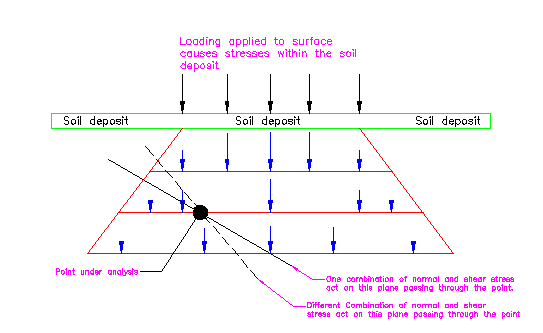 |
With increasing depth, the area over which new stresses are developed will increase, but the magnitude of the stress will decrease. For an equilibrium condition, the sum of the new vertical stresses developed in the soil mass on any horizontal plane must equal the weight or force of the surface loading.
Boussinesq Stress Distribution
One of the classical methods in common use for calculating stresses that result in a soil mass from a surface loading is based upon the work of Boussinesq, a nineteenth -century French mathematician. Boussinesq assumed a homogenous, isotropic material (properties the same in all directions) of semi-infinite extent (unlimited depth) and develop equations for the stress distribution resulting from a point load. Adapted to soil masses, the described conditions are indicated by the following figure. The vertical stress increase Δσv resulting at a depth Z and a distance r, measured horizontally from where a point loading Q is applied, becomes:
|
|
This equation indicates that as the depth increases the stress decreases. Similarly, the stress decreases as the horizontal distance from the point of loading is increased. For a given septh, the intensity of stress is greatest directly beneath the point of load application.
The suitability of using the Boussinesq equation for determining subsurface stresses in a foundation analysis depends on how closely the actual soil conditions and properties resemble the theory's original assumptions. For practical problems, conditions of a homogeneous and isotropic material are commonly assumed for homogenous clay deposits, for human-made fills where soil fill has been placed and compacted in thin layers, and for limited thickness of uniform granular soil deposits.
Westergaard Stress Distribution
Some sedimentarty soil deposits consist of alternating thin layers of sandy soil (coarse, relatively incompressible soil material) and fine-grained silt-clays (compressible material) - for example, stratified deposits such as laminated clays. For such conditions, the Westergaard equations provide a better means of evaluating the subsurface stresses. In his development, Westergaard assumed that thin layers of a homogeneous and anisotropic material were sandwiched between closely spaced, infinitely thin sheets of rigid material that would permit compression but no lateral deformation.
|
|
|
|
Class example Problem:
A 200 kn concentrated (point) load acts on the surface of a soil mass. Determine the vertical stress 3m below the ground surface at locations directly beneath the point of load application, 3 meters horizontally from the load, and 6 meters horizontally from the load. Perform calulations for both Boussinesq and Westergaard methods.
|
|
Application for Foundation Loading
In construction practice, the condition of a concentrated point loading is rarely encountered . More commonly, building loads are supported on foundations that cover a finite area (square, rectangular, or round footing), or the structure itself directly imposes loading over a finite area (earth structures such as dams and dikes). The subsurface stresses that result from loading acting over an area can be determined by integration of Equation shown above, where the loading on infini tely small increments of the foundation area can be assumed as point loads. The subsurface stress at a poi nt is the summation of the effects resulting from all of the applied point loadings. Such integrations have been accomplished for u niform loads acting on square, rectangular, strip, and circular areas, and also for u niformly varying loads such as those developing from the weight of an earth structure havi ng a sloped cross section (dams and dikes, for instance). Resul ts are available in the form of charts, tables, and graphs in order to provide generalized solutions. In these presentations, the subsurface stresses are expressed as a percentage of the foundation loading intensity. Measurements of the depth and horizontal distance at which a subsurface stress acts are expressed in terms of the dimensions of the loaded foundation area. Subsurface stress conditions indicated by Boussinesq and Westergaard equations for commonly occuring foundation loadings are presented in the figures below.
|
|
|
| Variation of Vertical Stress Beneath a Foundation: Boussinesq Analysis | Variation of Vertical Stress Beneath a Foundation: Westergaard Analysis |
Class example Problem:
A 300 kn loading is supported on a 1.5m by 1.5m square foundation constructed on the ground surface of a homogenous soil deposit (soil unit weight is 19 kN/m3). Determine the values of the pre-construction post-construction vertical stress imposed on the soil at a point 2m below the center of the foundation (assume Westergaard condition apply).
A long strip footing foundation will be used to support a masonry bearing wall for a commercial building. The footing will be 1.5m wide and 45m long. The wall loading imposed onto the foundation will be 200kN per meterof wall length. Determine the vertical stress increase from poins 1m, 2m, and 4m below the footing center, assuming: a. Boussinesq conditions apply b. Westergaard conditions apply
|
|
Combined Stresses in Soil Masses (Last Lecture)
The strength of a soil is a variable and elusive property. Strength characteristics of some materials are represented by simple concepts such as yield point, compression, or tensile strength. A given grade of steel is an example, Other materials, such as concrete, are considered in a similar fashion. Concrete strength, though, is very much subject to the quality of its components, their proportions, and the workmaqnship that goes into its manufacture, as is also the case with asphalt. The end product is more variable for concrete than it is for steel, even though the strength for both materials is expressed as a simple single number, relating to compressive or tensile strength.
With the exception of compacted fills, we deal with soils as they are in nature. Because they are not manufactured products, variations in properties are the rule, not the exception. They are natural materials and in most cases we use what is available, adjusting our designs and working methods to accomodate conditions. Soil strength is not described in a simple single value of tensile strength or compressive strength. There are many kinds of strength tests, some of which apply to a limited number of soils. In the general case, soil strength may be determined in tests that permit the control of stresses on the test specimen. The unconfined compressive strength test which you have done or will do is one example.
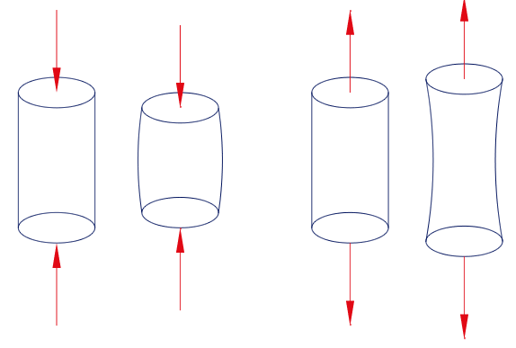
The objective of any soil strength test is to determine the shearing strength of the soil for a given set of conditions. When a soil is loaded to failure in a compression test, as shown in the diagram below, the stresses at failure are plotted on a Mohr diagram for interpretation. The corresponding Mohr circle is plotted and the strength envelope located.
 |
|
|
The effects of Compression on a Soil Mass
|
The Effects of Tension on a Soil Mass
|
 |
 |
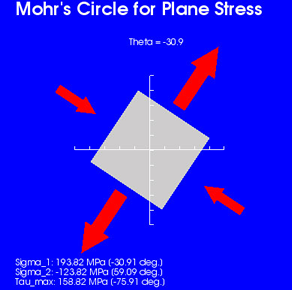
When a body or mass is subjected to external loading, various combinations of internal normal and shear stresses are developeded at different points within the body or mass. Generally, data concerning internal stress conditions are used to determine deformations and to check for the possibility of a material failure occurring because the strength is exceeded. In performing a stress study, it is convenient to use methods from engineering mechanics for analyzing stress at a point. With these methods, stresses acting on any plane passing through the point can be determined. The combinations of normal and shear stress that develop will vary, depending on the plane being analyzed and the magnitude of the external loading. The stress at a point analysis is also applicable for determining the weakest plane or potential plane of failure in a material, not always easily evident, and for indicating the magnitude of stress that act on this plane. This type of analysis has particular application for soil and foundation studies, since stability failures in soil masses are the result of the shear strength of the soil being exceeded.
The Analytical Development of Stress at a Point Within a Soil Mass
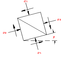
The stress acting on any plane passed through a point within a material consist of a normal stress which can be either compressive or tensile and a shearing stress. Depending on the type of external loading causing the stress condition, it is possible for the shear or normal stress or both to be zero on some planes. In soils problems, most external loadings are compression. For a situation where the loading is compressive, normal stresses that develop on any plane would almost always have a value other than zero; some shear stress would act on all planes with the exception of two planes, where it will be zero.
|
|
|
 |
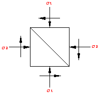 |
If the combination of normal and shearing stresses acting on any two mutually perpendicular planes is known, the combination of stresses acting on any other plane through the same point can be determined.
In analyzing stress at a point, it is convenient to assume an incremental element that represents the stress conditions at a point and to show the known stresses acting on it. For equilibrium, the sum of forces not stresses acting in any direction must equate to zero, and the rotational moments about any axis caused by forces similarly must equal zero. To satisfy this latter requirement, shear stress acting on orthogonal planes must be equal in magnitude.
 |
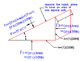 |
At the same point, but on a differently orientated element (actually a different plane passing through an identical location), the combination of normal and shearing stresses that act will be different. As will be shown, however, there is a relationship between the normal and shear stress acting on all planes (or orientation of elements) that pass through the same point.
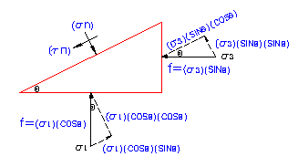
Consider all the planes that can be passed through a point. On one particular plane, not yet defined, the shear stress will be zero, whereas the normal stress will be the maximum possible value of all the normal stresses acting on the various planes through that point. On the plane perpendicular to the plane just referred to, the shear stress will also be zero, but the normal stress that acts will be the least, or the minimum, of all the normal stresses acting on different planes through the point. The maximum and minimum normal stresses are called the principal stresses. The planes on which they act are principal planes. The shear stress on a principal plane is always zero.
Normal Stresses (σ - sigma): Are the compressive stresses on the point under analysis. These stresses are also called principal stresses, and act on principal planes. Note that the shear stress on a principal plane is always zero.
Shear Stress (τ - Tau): Are stresses that can act on any plane other than a princpal plne and have a magnitude.
 |
|
|
Resolution of principal stresses into components parallel and perpendicular to a random plane
Class example Problem:
At a point in a stressed material the major principal stress is 30 kpa (compression) and the minor principal stress is 15kpa (compression). Determine the maximum shear stress that acts through the point and the normal stress on the plane of this maximum shear.
At a point in a stressed material the principal stress is 50 kpa (tension) and the minor principal stress is 24 kpa (tension). Calculate the maximum shear stress that acts through the point and the normal stress on the plane of maximum shear.
In many practical soil problems, the principal stresses actin the vertical and horizontal conditions (or on horizontal and vertical planes) and are easily calculated. For instance, where the incremental element represents a point within a soil mass where the ground surface is horizontal, the vertical stress is due to the soil overburden at that point. This would be the effective unit weight of the soil multiplied by the depth of the point below the ground surface. The horizontal stress is proportionate to the vertical stress. Therefore, the magnitudes of the principal stresses are known, as are the orientations of planes on which the stresses act.
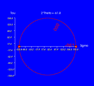
The varying values of normal stress and shear stress corresponding to differing values of theta can be determined by using the above equations. If the combination of normal and shear stress resulting from each value of theta is plotted on a coordinate system where the horizontal horizontal axis represents normal stress and the vertical axis represents shear stress, the locus of many plotted points will form a circle.
This fact can be used to advantage. By working with the simple properties of a circle, a graphical or pictorial method of solving for normal and shear stresses on any plane is easily developed once the stress on the orthogonal planes are known. This method simplifies the calculations necessary for determining stresses and eliminates the need to work with awkwardequations. This method is known as Mohr's Circle.
Steps to Constructing Mohrs Circle:
|
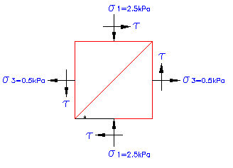
Mohr Circle Sample Problem: Determine the Normal and shear stress acting on a plane that is 60° clockwise from the major principle plane. With the shown stresses acting on the soil mass below construct a Mohr's Circle to solve the problem. |
|
 |
|